
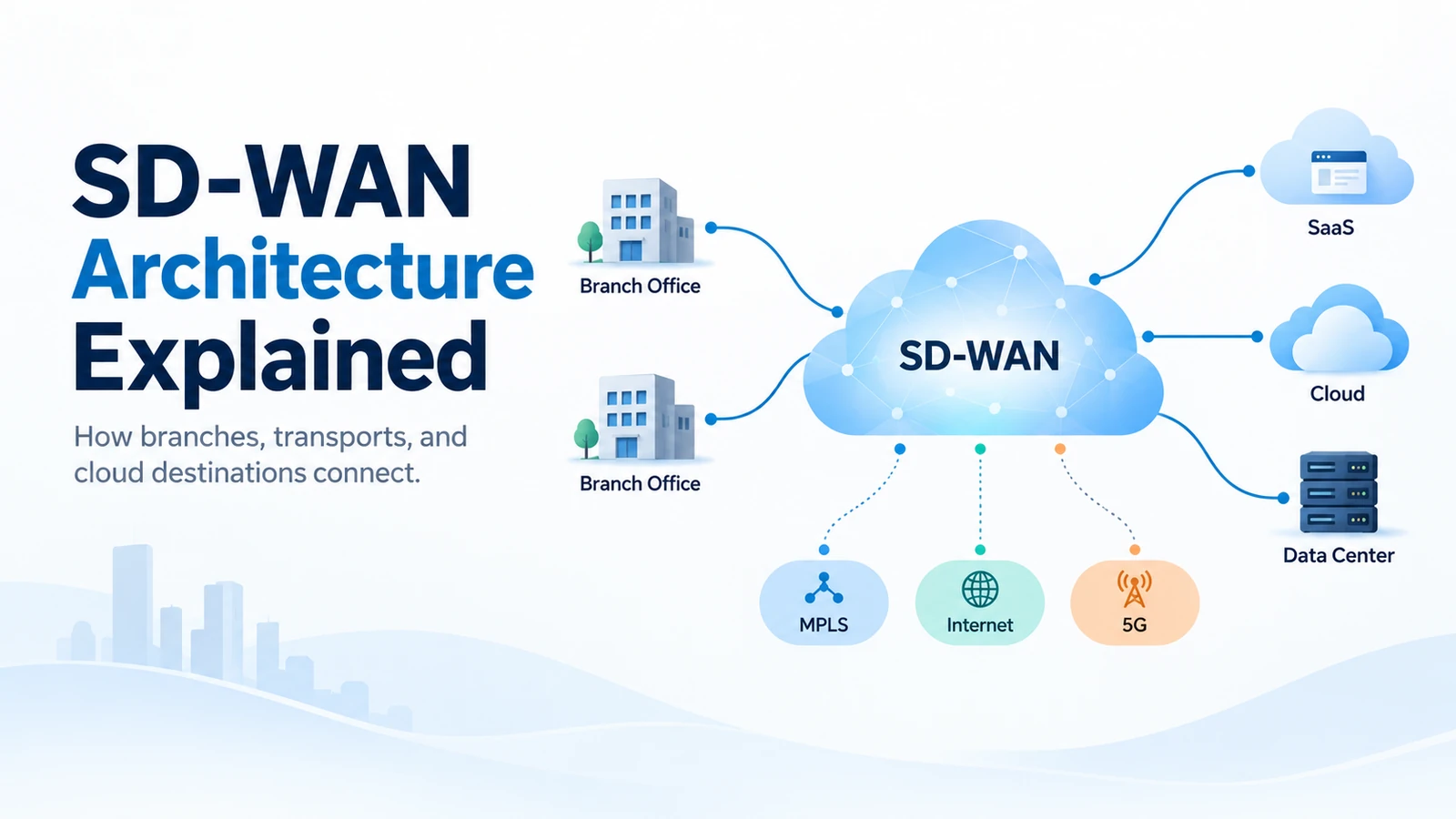
Software-Defined Wide Area Network (SD-WAN) architecture separates WAN connectivity from the policies that determine how applications use it. Instead of binding a branch to one preferred circuit or treating every WAN path in the same way, SD-WAN creates a software-controlled overlay across one or more physical underlay transports and applies centralized intent at distributed WAN edges.
That distinction is essential: SD-WAN is not the transport itself. MPLS, Dedicated Internet Access (DIA), broadband, fiber and 4G/5G can all provide the underlying connectivity. SD-WAN sits above those transports, building logical connectivity and deciding how application traffic should move across available paths.
Industry standards such as MEF 70.2 distinguish the SD-WAN service from the Underlay Connectivity Services over which it operates. Actual implementations differ by vendor, but the architectural principles—edges, policy, control functions, logical overlays and physical underlays—are broadly reusable.
Need the fundamentals first? Read our complete guide to SD-WAN before going deeper into the architecture.
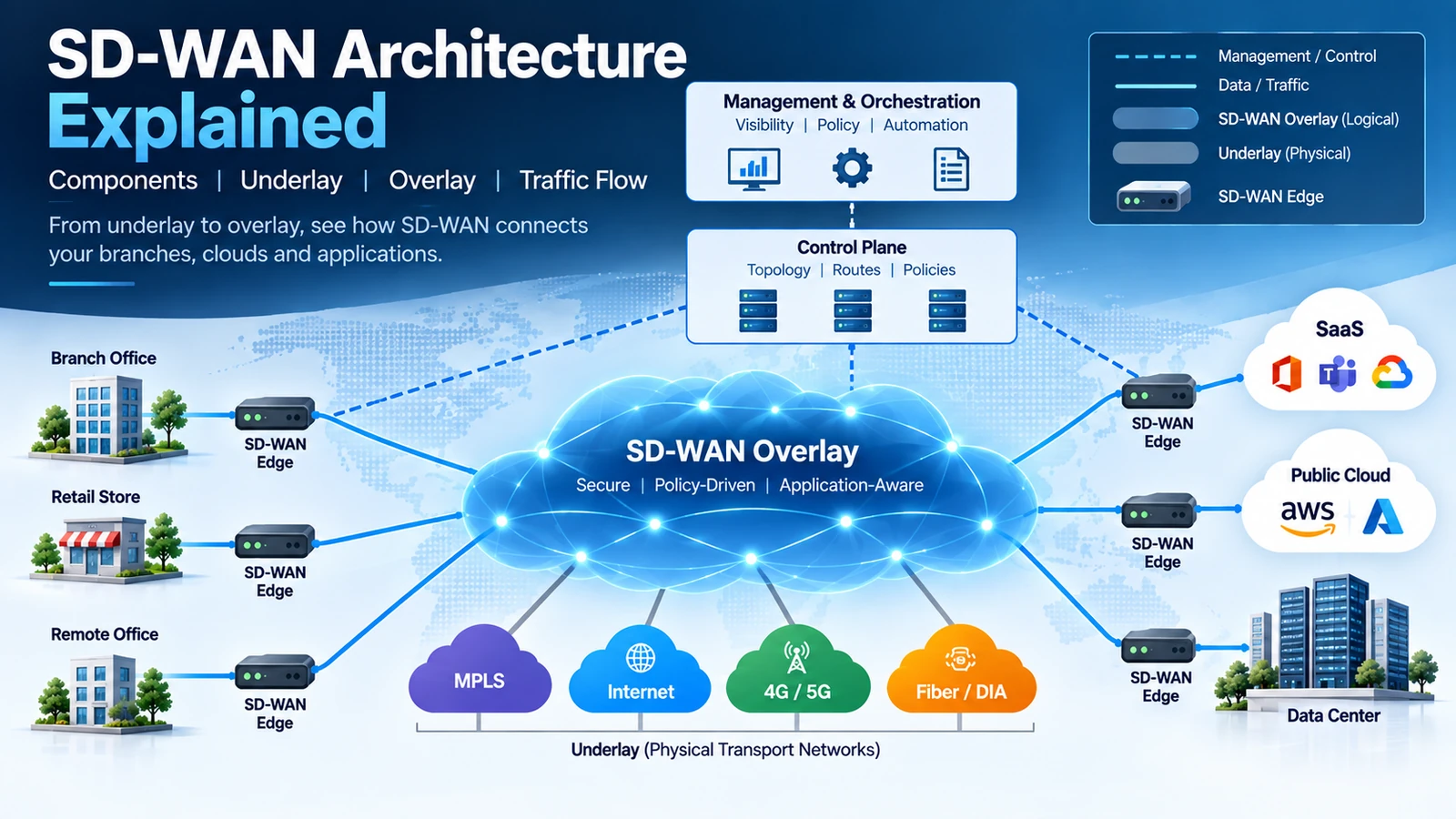
SD-WAN Architecture at a Glance
A practical way to understand SD-WAN architecture is to separate it into functional layers.
| Layer | Primary Function | Typical Components |
|---|---|---|
| Management / Orchestration | Configuration, visibility, lifecycle and operational control | Management platform, orchestrator, APIs |
| Control | Topology, routes, policies and control relationships | SD-WAN controllers or equivalent control functions |
| Data | Production traffic forwarding and policy enforcement | Physical or virtual SD-WAN edges |
| Overlay | Logical WAN connectivity across available transports | Tunnels, virtual topologies, segments |
| Underlay | Physical or carrier connectivity | MPLS, DIA, broadband, fiber, 4G/5G |
| Destinations | Applications and enterprise resources | SaaS, public cloud, data centers, branches |
The exact terminology varies by platform. Some products separate orchestration, management and control into distinct components, while others combine functions. Some architectures are cloud-hosted; others can run on-premises or in hybrid models.
Management defines intent → control distributes information → edges enforce policy → the overlay uses available underlays to carry application traffic.
The Main Components of SD-WAN Architecture
SD-WAN Edge
The SD-WAN edge is where the architecture meets production traffic. An edge can be a physical appliance at a branch, a device at a data center or regional hub, or a virtual instance deployed in a cloud environment.
Depending on the platform and design, it can perform functions including packet forwarding, tunnel termination, application classification, path-performance measurement, Quality of Service (QoS), routing, traffic-policy enforcement, segmentation and local internet breakout.
When an application flow arrives, the edge may identify the traffic, determine which policy applies, evaluate eligible paths and forward the traffic over the path that best satisfies the configured intent.
SD-WAN Controllers
Controllers commonly handle parts of the SD-WAN control function. Depending on the product, they may maintain topology information, exchange or distribute routing information, distribute centralized policies, establish secure control relationships with edges and influence how logical connectivity is built.
A controller should not be confused with the production traffic path. In many SD-WAN designs, application packets travel directly between WAN edges or through intentionally selected hubs or services. They do not need to pass through a centralized controller for every packet.
Management and Orchestration Platform
The management layer gives administrators a centralized operational interface to the SD-WAN environment. Typical capabilities include device onboarding, configuration templates, centralized policies, monitoring, analytics, software lifecycle management, inventory, alarms, troubleshooting and API-based automation.
The management plane is primarily concerned with operating the network, rather than forwarding user packets. An administrator may create a policy centrally, but the branch edge ultimately applies that policy to production traffic.
Gateways, Hubs and Cloud Edges
Some designs include regional hubs, cloud gateways, virtual WAN edges, service gateways or security service insertion points. These are useful architectural patterns, not universal SD-WAN requirements.
SD-WAN Underlay vs Overlay
Underlay and overlay are two of the most important concepts in SD-WAN architecture. Confusing them leads to a common misconception: that SD-WAN replaces the physical WAN. It does not.
What Is the SD-WAN Underlay?
The underlay is the connectivity capable of transporting packets between locations. Common underlays include MPLS, Dedicated Internet Access, business broadband, fiber access, LTE/4G, 5G and other suitable IP connectivity.
These networks still determine real physical characteristics such as available bandwidth, latency, congestion, packet loss and path diversity. SD-WAN can make better use of available transports, but it cannot turn a poor physical link into a high-quality one.
What Is the SD-WAN Overlay?
The overlay is the logical connectivity created across those underlays. Depending on the platform, it can include logical tunnels, virtual topologies, segments, policy-driven connectivity and application-aware forwarding.
Instead of binding an application to one fixed circuit, the architecture can express higher-level intent about which permitted paths an application should use.
| Underlay | Overlay |
|---|---|
| Physical or carrier connectivity | Logical connectivity |
| Provided through access/network services | Created by the SD-WAN architecture |
| MPLS, DIA, broadband, 4G/5G | Tunnels, segments and virtual topologies |
| Determines actual transport characteristics | Determines logical forwarding behavior |
| Provides reachability | Applies policy to that reachability |
MPLS therefore does not automatically disappear when SD-WAN is introduced. It can remain one of several underlays. For a deeper analysis, see where MPLS still fits in modern enterprise WANs.
Management Plane, Control Plane and Data Plane
Management Plane
The management plane provides the operational interface and commonly handles configuration, templates, monitoring, analytics, alarms, inventory, software lifecycle and policy creation.
Control Plane
The control plane handles information that determines how connectivity should operate. Depending on the implementation, this can include route information, topology information, reachability, policy distribution and control sessions.
Data Plane
The data plane forwards actual production packets. At the SD-WAN edge, this can involve receiving the application packet, identifying its traffic class, matching a forwarding policy, selecting an eligible WAN path, applying QoS and forwarding the packet through the overlay.
Administrator defines policy → management system stores the intent → control functions distribute relevant information → SD-WAN edges receive policy/topology state → edges forward production traffic.
Cisco Catalyst SD-WAN provides one concrete example of this separation using distinct orchestration, management, control and data-plane functions. That is an implementation example, not a mandatory architecture for every SD-WAN product.
Why Plane Separation Matters
Separating control and management functions from distributed packet forwarding enables enterprises to centralize policy without centralizing every packet. That can improve operational consistency, automation, network-wide policy management, topology control, scalability and visibility.
How an SD-WAN Overlay Is Built
- The edge comes online. It gains basic IP connectivity through one or more WAN transports.
- The edge is authenticated. The platform verifies that the edge is authorized to join the environment.
- Secure control relationships are established. The edge connects to the relevant management or control functions.
- The edge learns network state and policy. Routing, segmentation, application policies and topology instructions may be distributed.
- Logical connectivity becomes available. Overlay connectivity forms across one or more available underlays.
- Routing and segmentation become operational. The edge learns which destinations and segments it may reach.
- Production traffic can be forwarded. The edge now applies policy to real application flows.
The underlay gets the edge connected; the overlay determines how that connectivity participates in the SD-WAN fabric.
How Traffic Flows Through an SD-WAN Network
Consider a user at Branch A opening Microsoft 365. The application is only an example—the same architectural process can apply to other SaaS, cloud or enterprise applications.
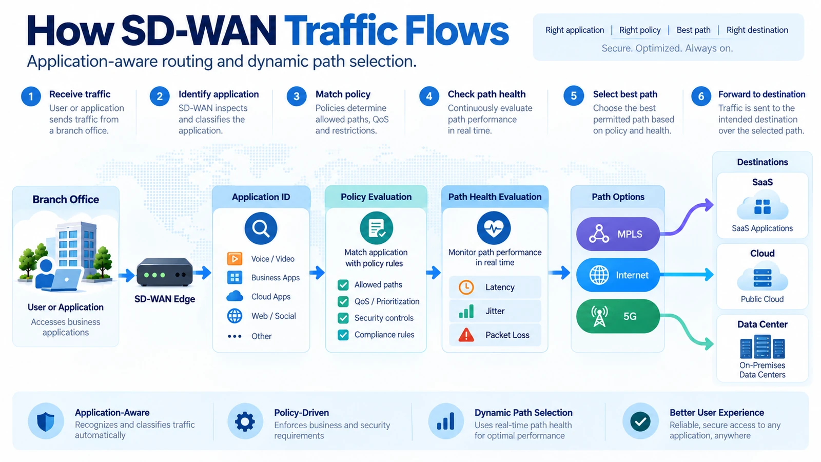
Step 1 — The Packet Reaches the SD-WAN Edge
The branch LAN routes the traffic toward the SD-WAN edge.
Step 2 — The Application or Traffic Class Is Identified
Depending on the platform and configuration, the edge may identify the application or classify the flow based on available traffic information.
Step 3 — Policy Is Evaluated
The edge determines which configured policy applies. Voice may require a low-latency path, ERP may prefer a high-quality path and SaaS traffic may be allowed to use direct internet access.
Step 4 — Eligible Paths Are Evaluated
Suppose the branch has MPLS, DIA and 5G backup. The edge determines which of those paths are eligible for the application.
Step 5 — Path Conditions Are Considered
Many platforms can use performance information such as latency, jitter, packet loss, reachability and policy preference. The exact probes, measurements and thresholds vary by platform.
Step 6 — The Best Permitted Path Is Selected
The important word is permitted. SD-WAN does not simply choose whichever circuit looks fastest; policy constrains the choice.
Step 7 — Traffic Is Forwarded
The edge forwards traffic over the selected logical path toward SaaS, cloud, a data center or another enterprise location.
Step 8 — Path Health Continues to Be Monitored
Congestion, carrier incidents and packet loss can change during the day, so path conditions are continuously relevant.
Step 9 — Forwarding May Change
If a path no longer satisfies configured conditions, the platform may select another permitted path. Switching behavior varies, so seamless or lossless failover should not be assumed in every circumstance.
Application-Aware Routing and Dynamic Path Selection
Traditional routing is fundamentally concerned with destination reachability. SD-WAN can add application and performance context to that decision.
- Voice: prefer low latency and low jitter.
- Business-critical ERP: use a stable high-quality path, potentially with a preferred transport.
- Web and SaaS: use efficient direct internet access where security and policy allow it.
- Backup traffic: use cost-efficient available capacity.
Typical path-selection inputs can include latency, jitter, packet loss, reachability, administrative preference, application class and configured SLA thresholds. Not every platform uses these metrics in the same way.
Brownouts vs Complete Failures
A circuit can remain technically up while performing poorly due to excessive latency, high jitter or significant packet loss. SD-WAN may be able to react to such a brownout, but the exact behavior depends on platform capabilities, measurements and configured policy.
Common SD-WAN Topology Models
Hub-and-Spoke
Remote branches communicate primarily through one or more centralized hubs. This can simplify shared-service insertion but may create unnecessary backhaul for cloud traffic.
Full Mesh
Sites can communicate directly with many or all other sites. This can reduce unnecessary hub traversal but may increase policy and operational complexity.
Partial Mesh
Only selected sites communicate directly. This balances direct connectivity and control in larger enterprises.
Regional Hub Architecture
Branches connect to regional hubs rather than one global hub. This can reduce long-distance backhaul for multinational environments.
Cloud-First / Direct-to-Cloud Architecture
Branches access SaaS and cloud services directly where policy allows while using the overlay for other enterprise traffic. This can improve path efficiency but changes the security architecture.
Branch, Data Center and Cloud Connectivity
Modern enterprise applications are distributed. A branch may need to reach data centers, SaaS, public cloud workloads and other branches, while cloud edges may need controlled connectivity back to the enterprise WAN.
When most applications lived in enterprise data centers, centralized backhaul was logical. With significant SaaS and public-cloud adoption, sending all internet-bound traffic through a distant data center can create inefficient paths.
SD-WAN makes more flexible traffic patterns possible, but security must follow the new architecture. See SD-WAN vs SASE for the broader networking/security relationship.
Segmentation in SD-WAN Architecture
SD-WAN can support multiple logical traffic domains across shared physical WAN infrastructure. Common examples include Corporate, Guest, Voice, IoT, Operational Technology and regulated workloads.
Logical segmentation can influence which routes are visible, which destinations are reachable and which application policies apply. Segmentation can contribute to a broader security architecture, but SD-WAN segmentation alone is not a complete cybersecurity strategy.
High Availability and Resilience
SD-WAN gives architects more options for using multiple WAN paths, but resilience still has to be designed across multiple transports, redundant edges, controllers or management systems, hubs and cloud paths.
Logical Redundancy Is Not Physical Diversity
Two circuits are not automatically resilient because they have different service IDs or even different providers. They may enter the building through the same duct, use the same local fiber, traverse the same carrier node or depend on shared access infrastructure.
SD-WAN can use multiple available transports intelligently. It cannot compensate for physical diversity that was never built.
SD-WAN Architecture Example: A 40-Branch Enterprise
Consider a fictional enterprise with headquarters, two data centers, 40 branches, Microsoft 365 and other SaaS applications, plus workloads in Azure and AWS.
- Large branches: MPLS + DIA.
- Standard branches: dual internet.
- Small sites: internet + 5G backup.
Across all sites, the enterprise uses centralized management, distributed SD-WAN edges, centralized policy intent, logical overlay connectivity, segmentation, direct SaaS access where permitted, data-center connectivity and cloud connectivity.
A user at Branch 12 launches Microsoft 365. The edge identifies the traffic and matches the relevant SaaS policy. If DIA is healthy and meets the configured performance requirements, traffic is forwarded directly toward the internet instead of being backhauled through a data center. If the DIA path later develops significant packet loss, another permitted path may be selected.
Planning to turn the architecture into a migration project?
Download the Free SD-WAN Migration Checklist and Cutover Planner to structure assessment, pilot, cutover, validation and rollback planning.
Traditional WAN vs SD-WAN Architecture
| Architecture Dimension | Traditional WAN | SD-WAN |
|---|---|---|
| Control | Primarily device/routing driven | Centralized intent with distributed enforcement |
| Path selection | Primarily routing/reachability based | Can include application and performance context |
| Transport | Often closely coupled to design | Multiple transports can participate in one overlay |
| Cloud access | Frequently centralized/backhauled | Direct access can be policy controlled |
| Visibility | Often device and circuit oriented | Application/path visibility can be centralized |
| Policy | Frequently configured across devices | Centralized policy models are common |
| Operations | Device-by-device workflows common | Template and orchestration models are common |
For the complete comparison, read SD-WAN vs Traditional WAN.
Where SASE Fits into the Architecture
SD-WAN primarily focuses on WAN connectivity, overlay networking, application-aware traffic steering and branch/cloud connectivity. Secure Access Service Edge (SASE) expands the architecture by combining networking with cloud-delivered security capabilities.
The distinction becomes especially important with direct internet breakout. For the detailed comparison, read SD-WAN vs SASE and our complete SASE guide.
Is SD-WAN Architecture Vendor-Neutral?
The architectural principles can be explained in vendor-neutral terms. The implementation cannot. Platforms may differ in controller architecture, routing protocols, tunnel technologies, authentication, management architecture, policy models, application classification, analytics, cloud integration, security integration and failure-detection mechanisms.
The concepts are reusable. The implementation details are not universal.
Common SD-WAN Architecture Mistakes
| Mistake | Why It Matters | Recommended Approach |
|---|---|---|
| Treating SD-WAN as a cure for poor underlays | Software cannot eliminate congestion or inadequate bandwidth | Engineer underlay capacity and quality deliberately |
| Using one branch design everywhere | Sites have different users, applications and criticality | Define branch profiles |
| Ignoring physical diversity | Two logical links may share the same failure domain | Verify carrier and access diversity |
| Designing security after local breakout | Internet traffic may bypass legacy centralized controls | Design networking and security together |
| Overcomplicating segmentation | Too many segments increase operational complexity | Segment according to real requirements |
| Poor cloud routing design | Cloud traffic can still take inefficient paths | Model cloud flows explicitly |
| Ignoring operational visibility | Dynamic policy is difficult to operate without telemetry | Design monitoring from the start |
| No failure testing | A theoretical backup path may not work as expected | Test circuit, edge, hub and controller failures |
| Misunderstanding application policies | Incorrect thresholds can produce unexpected routing | Validate policies with real application behavior |
| Assuming every path is equal | Internet, MPLS and cellular paths differ | Match applications to appropriate path classes |
How to Read an SD-WAN Architecture Diagram
- Find the WAN edges. Identify devices or virtual instances forwarding production traffic.
- Find management and controllers. These systems manage or distribute control information; production packets do not necessarily traverse them.
- Identify the underlays. Look for MPLS, DIA, broadband, fiber or 4G/5G transports.
- Identify the overlay. Separate logical site-to-site relationships from physical access circuits.
- Separate control relationships from data flow. A clear diagram should distinguish management/control communication from application traffic.
- Look for segments. Identify separate logical networks for different workloads.
- Find the destinations. SaaS, public cloud, data centers, internet and other branches are common endpoints.
- Follow one application flow. Trace edge → policy → available paths → chosen transport → destination.
For TechTeamSynergy diagrams, dashed lines represent management/control relationships and solid lines represent production/data connectivity. This is our visual convention, not an industry standard.
Frequently Asked Questions About SD-WAN Architecture
What is SD-WAN architecture?
SD-WAN architecture is a software-controlled WAN model that uses distributed WAN edges, centralized management or control functions, and a logical overlay across one or more physical underlay transports.
What are the main components of SD-WAN?
Common components include SD-WAN edges, management/orchestration platforms, control functions or controllers, overlay connectivity and underlying WAN transports. Exact terminology varies by vendor.
What is an SD-WAN edge?
An SD-WAN edge is a physical or virtual device that forwards production traffic at a branch, data center, cloud environment or hub.
What is an SD-WAN controller?
An SD-WAN controller typically participates in centralized control functions such as topology, route or policy distribution. Exact responsibilities vary by platform.
What is the difference between SD-WAN underlay and overlay?
The underlay provides physical or carrier connectivity, while the overlay provides logical SD-WAN connectivity and policy across those transports.
What is the SD-WAN control plane?
The control plane handles network information that influences connectivity, such as topology, reachability, routes and policies.
What is the SD-WAN data plane?
The data plane forwards actual production packets, typically through distributed SD-WAN edge devices.
Does SD-WAN replace MPLS?
Not necessarily. MPLS can remain one of the underlays used by an SD-WAN architecture alongside DIA, broadband or cellular connectivity.
Does SD-WAN require internet?
No single transport is mandatory. SD-WAN requires suitable connectivity between relevant components and destinations, which can include MPLS, private connectivity, internet or other supported underlays.
How does SD-WAN choose the best path?
Depending on platform and policy, an edge may evaluate application class, path eligibility, latency, jitter, packet loss, reachability and configured preferences before selecting a permitted path.
Is SD-WAN full mesh?
It can be, but it does not have to be. Designs can use full mesh, hub-and-spoke, partial mesh, regional hubs or other logical topologies.
How does SD-WAN connect to cloud applications?
Branches can use policy-controlled paths to reach SaaS directly or reach cloud workloads through public/private connectivity, virtual edges, hubs or cloud gateways depending on the architecture.
Where does SASE fit with SD-WAN?
SD-WAN primarily provides WAN connectivity and traffic steering. SASE expands the architecture by combining networking with cloud-delivered security capabilities.
Conclusion: A Simple SD-WAN Architecture Model
UNDERLAY
provides physical or carrier connectivity
↓
OVERLAY
creates logical WAN connectivity across available transports
↓
CONTROL
distributes topology, routes and policy information
↓
POLICY
expresses how applications are intended to use the WAN
↓
EDGE / DATA PLANE
forwards actual production traffic
The important point is that production packets do not need to travel through a centralized controller simply because policy is centrally managed. SD-WAN separates WAN intent from individual transport circuits, allowing enterprises to operate MPLS, internet, broadband and cellular connectivity as parts of a more policy-driven WAN fabric.
Continue Learning
What Is SD-WAN? Complete Guide
Start with the fundamentals of SD-WAN, including benefits, use cases and its role in modern enterprise networking.
SD-WAN Migration Checklist
Move from architecture to execution with a practical checklist covering assessment, pilot, cutover, validation and rollback planning.
SD-WAN vs SASE
Understand where SD-WAN ends, where SASE begins and how networking and cloud-delivered security can work together.
SD-WAN vs Traditional WAN
Compare routing, transport, cloud access, operations and application-aware path selection in traditional and software-defined WAN architectures.
Is MPLS Dead?
See where MPLS still fits in hybrid WAN designs and how it can coexist with SD-WAN as an underlay.
SD-WAN vs Managed SD-WAN
Compare self-managed and provider-managed operating models and decide who should run the SD-WAN environment.